Wednesday, 29 February 2012

Wireless sensor node - prototype node (9)

It's finally time to build my first proper prototype wireless sensor node. The components are as follows:
  • CR2032 3V battery + battery holder
  • ATtiny85 MCU + 8 pin socket
  • TMP36 temperature sensor + 3 pin female header
  • 315MHz RF TX module + 4 pin female header
  • A small amount of tripad board
The process of soldering these parts together went quite smoothly. And yes, that is some beer brewing beside me!


 The results without any parts in place looks like this.


And this is what it looks like with all the parts in place.


I'm fairly pleased with how neat the soldering turned out.


Sadly having built this I found that the RF TX no longer worked reliably and the temperature sensor wasn't reporting accurate readings! This required some software fixes!

1) Fixing the RF TX

I have historically used a scheme where I sent three 16 bit values and then combined them at the receiver. However, the Manchester lib now supports sending longer messages so I've retired my pointless message combining code and simply send a single longer message.

2) Getting accurate readings out of the TMP36

The basic method for getting temp readings is as follows.

  int sensorValue = analogRead(TmpPin);
  // Constant: 5000 / 1024
  float milliVolts = sensorValue * 4.8828125;
  float tempC = (milliVolts - 500) / 10;
  return tempC;


The crucial change to make when running on an ATtiny85 is to change the constant which adjusts for the reference voltage being used which in my case is certainly not 5V!

First, add the following to your setup method. This tells the ATtiny85 to use the internal 1.1V reference voltage in preference to the VCC which will change as our battery runs down.

  // Select the 1.1V internal ref voltage
  analogReference(INTERNAL);


Secondly, update the temp reading code as follows.

  int sensorValue = analogRead(TmpPin);
  // Constant: 1100 / 1024
  float milliVolts = sensorValue * 1.07421875;
  float tempC = (milliVolts - 500) / 10;
  return tempC;

3) Getting more accurate readings out of the TMP36

The ATtiny85 internal 1.1V reference voltage isn't very accurate so it's worth calibrating the constant you are using. To do this I took a temperature reading from the TMP36 when connected to my ATtiny85 and when connected to an Arduino Uno. I then used the following formula:

V_calib = V_base * ((T_ref + 50) / (T_base + 50))
V_base = 1100
T_ref = temp as measured on Arduino Uno
T_base = temp as measured on ATtiny85

I ended up with V_calib = 1028 which gave me fairly accurate temp readings.

The results?

A working wireless sensor node! (I have added a ~20cm antenna wire since the previous pictures)


I have tested this node briefly but I won't deploy it until I do some more work.

For the wireless sensor node I want to build an enclosure.

For the base station I want to build an enclosure and write code to handle storing readings and allowing download over bluetooth.

As ever, the Arduino code is available on Github:

Monday, 27 February 2012

Wireless sensor node - watch battery (8)

Back in part 4 I made some improvements and did some sums and convinced myself that I could run my TX node on 3x AA batteries for more than a couple of years. Here are the sums I used.

Entering the following figures into this website:
  • Battery capacity: 1700mAh
  • Sleep current consumption: 0.006mA
  • Wake current consumption: 8.5mA
  • Duration of wakeup: 2000ms
  • Number of wakeups per hour: 12 (once every 5 minutes)
The result: 2.6 years.

It occurred to me that the wakeup time of two seconds is pretty long. I used this time to allow for 3 transmissions with high power sleeps between them. However, if I use low power sleeps between retransmits I can be running at high power for a much shorter time and hence get a much better battery life. The results are pretty impressive.
  • Battery capacity: 1700mAh
  • Sleep current consumption: 0.006mA
  • Wake current consumption: 8.5mA
  • Duration of wakeup: 100ms
  • Number of wakeups per hour: 36 (once every 5 minutes * 3 transmissions of each reading)
The result: 11.38 years! It seems pretty unlikely that my batteries would actually last for a decade but this long battery life means that I could get away with a much smaller battery. A single CR2032 watch battery is very cheap, 3V and usually has a capacity of 225mAh.
  • Battery capacity: 225mAh
  • Sleep current consumption: 0.006mA
  • Wake current consumption: 8.5mA
  • Duration of wakeup: 100ms
  • Number of wakeups per hour: 36 (once every 5 minutes * 3 transmissions of each reading)
The result: 1.51 years! That's an ideal length of time - I think I'll be using CR2032 batteries with my wireless TX node.

Sunday, 26 February 2012

Wireless sensor node - new hardware (7)

In my last wireless sensor node post I described the compact breadboard layout which I had come up with for prototyping. This layout allowed me to program my ATtinty85, run my ATtiny85 RX TX and run my Arduino RX. However, this was really cumbersome and I don't want to tie up my Arduino Uno for ever. It's time to break out my TX and RX nodes into their own circuits.

Firstly I have my base station RX node based around my new Arduino Pro Mini. This has the following parts:
  • Breadboard
  • RF RX module
  • Arduino Pro Mini
  • One of:
    • FTDI cable for programming + power
    • USB breakout board for power + Bluesmirf Silver Bluetooth module for wireless comms with the board
The results look like this with the FTDI cable.


The extra bit of tripad board here is because I don't have any double sided male headers.


 The base station looks like this with the Bluetooth module and USB power.


The wireless TX sensor node itself continues to be based around an ATtiny85. However, now that I have a dedicated USBtiny programmer I can use the following circuit for conveniently prototyping the TX board. This has the following parts.
  • Breadboard
  • RF TX module
  • ATtiny85
  • One of:
    • USBtiny for programming + power
    • Battery pack for power
The results look like this with the USBtiny programmer:


The TX node looks like this with the battery pack.

Saturday, 25 February 2012

Making it easier to program an ATtiny85

Ever since I got started with an ATtiny85 I have been using my Arduino Uno to do the programming. One of my friends has been through several iterations to make programming an ATtiny as easy as possible. This culminated in him building something he called the "Frankentiny".

I have finally invested in a dedicated USBtiny programmer (~£10).


This exposes a standard 6 pin programming header. This requires you to build a circuit to interface between the 6 pin connector and an ATtiny85. The pins are as follows.


I built the following circuit on some tripad board:


This includes a 4 pin header to expose pins 3 and 4 which are unused and expose VCC and GND.

Friday, 24 February 2012

Oculus Robot

I just came across a cool product called the Oculus Robot. This reminded me of the Big Bang Theory episode where Sheldon builds himself a Mobile Virtual Presence Device.


For around £175 you can get yourself a remote controllable platform for your netbook.


Thursday, 23 February 2012

Arduino Pro Mini serial pins

In my previous post I described the Arduino Pro Mini. I have now bought one of these and want to get started with it. However, the Pro Mini does not include a built in USB to serial connection. 

To get started you need to get an external USB to serial connector. This can come in the form of a cable or a breakout board. These will often be referred to as FTDI cables or FTDI breakout boards. This is actually an abbreviation for the name of the company (Future Technology Devices International) which makes the most common USB to Serial chips. 

The latest breakout boards come with a female header, older versions featured through hole connections which required you to solder on your own header. The cable normally comes with a female header. In both cases the Pin out should match up with the 6 pins on the end of a Pro Mini to allow for a direct connection to be made. 

The headers which you use for the FTDI connections on your Pro Mini will depend on the way that you intend to use the Pro Mini.

Here are some pictures of possible solutions from these pages.

Right angle male header with an FTDI breakout:


Regular male header with an FTDI cable:


I chose to attach female headers to my Pro Mini so that I could use my non Mate Bluesmirf Bluetooth module which I have previously soldered wires to. 


If you have a Bluesmirf Mate then you can connect the pins directly. The non Mate version requires that you flip a couple of the pins as described in this excellent blog post.


Wednesday, 22 February 2012

Soldering

My last two posts have talked about the Arduino Pro Mini and some background about headers and mounting. To put these together you are probably going to need to do some soldering. 

So what do you need to do soldering?
  • Soldering Iron - tool used to melt the solder. 
  • Solder - material which is melted by the iron and used for soldering. 
  • Solder Wick - material which is used to remove excess solder
  • Flux - material which is used to prime a surface for soldering
The second two of these are technically optional but they are both cheap and having them available will make your life easier. 

The general process for soldering is as follows.
  • Prepare the joint to be soldered - make sure it is held steady and won't move as you attempt to solder it. You may find this tricky - I always wish I had a 3rd or 4th hand!
  • (Optional) Apply a little flux to the joint. This is a mild acid which will clean the joint and allow a better solder connection to form. Solder won't bond with an oxidized or dirty surface.
  • Preheat the iron. Soldering is all about heat so don't try to start until your iron is nice and hot. 
  • Touch a small amount of solder to the tip of the iron. This is called "tinning" the iron and ensures good heat conductivity. 
  • Press the iron onto the joint to be soldered. 
  • After a second or two, press the solder onto the other side of the joint. The solder should be melted by the joint being hot enough rather than directly by the iron. If you touch the solder to the iron it will likely just vaporise/stick to the iron.
  • Remove the solder from the joint first. 
  • Then remove the iron.
There are a lot of good soldering videos on YouTube. Here are a few which I have found useful.


Tuesday, 21 February 2012

Headers and Mounting

Headers

In my previous post I gave a quick overview of the Arduino Pro Mini. This board features through hole connectors without any headers attached. Therefore, to connect anything to the board it is necessary to solder on some headers - but what kind?

As ever, there is a lot of choice (there is always so much to choose from with electronics!). The key things to decide on are the following.
  • Gender - female headers are good for wiring into a breadboard, male headers can be inserted directly into a breadboard.
  • Orientation - angled headers allow a connection to be made in line with a board rather than at right angles.
  • Special types
    • Stackable headers provide a regular female header with a male pin long enough to expose a male header below the board. 
    • Double sided male headers - these allow you to connect female headers together. 
As a minimum you will probably just need some regular female and male headers. Any additional headers will depend on your project.

Mounting

The main thing you have to consider when choosing headers is what you are planning to mount your components on. The main mounting options are the following.
  • Breadboard - solderless board where components can be wired together
  • Stripboard which comes in several varieties - components have to be soldered to the board
    • Plain - each hole is isolated and components must be wired/soldered together on the board 
    • Strip - strips of holes are connected by metal tracks
    • Tripad - strips of 3 holes are connected by metal tracks. This is a good compromise between plan and strip
  • PCB - if you have a specific circuit planned out you can get a custom PCB produced which you can mount your components on
Your choice of mounting will likely be guided by the desired final size, cost and whether you are comfortable soldering components. 

I have done a bit of soldering with Tripad boards with moderate success. However, it's hard to beat the convenience of a breadboard.

Inspiration

When I got my Arduino Pro Mini I wasn't sure about the best connectors to solder onto the pins. In the end I decided to attach female headers to all of the pins to make it easy to wire the Pro Mini into other components with normal jumper wires. The very next morning I came across a Sparkfun article about the Pro Mini which featured the following picture.

I think this picture actually shows off a couple of great ideas.
  • Attaching male headers to the Pro Mini allows the board to plug directly into a breadboard. I may try this with the next Pro Mini which I buy.
  • Attaching right angled male headers on one side of a chip allows it to be mounted in a very compact way. Mounting female headers on the other side would allow jumper cables to be used to connect any extra pins which were needed.
This picture also reminded me that a breadboard is a really easy way of putting together a circuit. I had previously assumed that I should end up building my final circuits on stripboard or even a PCB but I'm starting to realise that for most projects it will be much easier to just setup a suitably sized breadboard.

Monday, 20 February 2012

Arduino Hardware

Arduino Uno

The first Arduino board which I got was an Arduino Uno. This is the standard starter Arduino and comes with the following key specs:

- ATmega328 running a 24Mhz
- 14 digital I/O pins, 6 analog I/O pins
- built in USB to serial chip and USB socket
- built in DC power jack
- built in ICSP header
- built in reset button

All of the Uno's pins come prefitted with female headers that make it perfect for connecting to a breadboard or for stacking Arduino shields on top. 
Price: ~£23. From a quick Google search there are loads of sites sell this board.

Arduino Pro Mini
The Arduino Pro Mini packs most of the punch of an Uno in a smaller, cheaper, more flexible package. I have recently bought one of these but I haven't actually programmed it yet.
Briefly here are the key specs:

- ATmega168 or 328 running a 16mhz (5V edition) or 8Mhz (3.3V edition)
- 14 digital I/O pins, 6 analog I/O pins without any headers presoldered on
- built in reset button

The key difference is the lack of built in connectors. This means the chip can be much smaller and the lack of headers provides much more flexibility.
Price:  ~£14. From a quick Google search there are lots of sites selling this board.

Arduino Nano

The Arduino Nano is a nice compromise between the Uno and the Pro Mini. I have just found out about this board by browsing the Arduino hardware page as part of writing this article.

Briefly here are the key specs:

- ATmega168 or 328 running at 16Mhz
- 14 digital I/O pins, 8 analog I/O pins
- built in USB to serial chip and USB socket
- built in ICSP header
- built in reset button
The main difference compared to an Arduino Uno is the lack of a DC power jack and the physical format - this is a very long (15 breadboard pins) thin board!

This actually looks like an ideal board for the base station of my planned home wireless sensor network! I had been planning to use an Arduino Pro Mini which requires a separate FTDI cable and USB breakout board. However, the Nano has both of these parts built in and only costs an extra £3 compared to a Pro Mini! However, given that I already have a Pro Mini + USB breakout board and have an FTDI cable in the post I may delay switching to an Arduino Nano until a later upgrade of my base station.
Price: ~£17. From a quick Google search there don't seem to be many sites selling this board.

Size Comparison
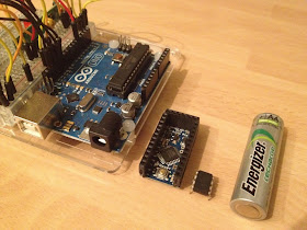
I currently own an Arduino Uno and I have been playing around with standalone ATtiny85 microcontrollers. A few days ago I bought an Arduino Pro Mini which I haven't done anything with yet but solder on some female headers. 
Here is a photo of my Arduino Uno, Arduino Pro Mini and a single ATtiny85 side by side with an AA battery to show off the relative size.

Tuesday, 7 February 2012

Non-Newtonian fluid

I was watching an old episode of The Big Bang theory this evening and the following clip caught my attention.


Better quality: http://www.youtube.com/watch?v=eA1jSlx9c30 (I can't embed this version)

It turns out that it is possible to mix up a non-newtonian fluid very easily at home using only corn flour and water in a ratio of about 2:1. Non-newtonian fluids are really weird substances - under pressure they act as solids. You can grab what feels like a lump in the liquid and have it flow out of your fingers as soon as you stop applying pressure. You can also tap the surface of the liquid without getting wet but if you press gently your finger sinks into the liquid. The most interesting effect is that if you vibrate a non-newtonian liquid the pressure waves cause the fluid to form really cool structures. I don't have a great speaker for doing this but I still managed to do the following.


Here are some better videos from people with much more suitable speakers.


Sunday, 5 February 2012

Wireless sensor node - background rx (6)

I have started to think a bit more about deploying my wireless sensor network. My plan is still to deploy multiple cheap ATtiny85 based RF transmitting, battery powered sensor nodes. These will talk to an Arduino base station which will receive the readings. 

The base station needs to save the readings to an SD card, allow bulk uploads over Bluetooth and will possibly in future drive a screen. None of these things will be possible if the Arduino has to spend all its time blocked listening for readings from the sensor nodes. Therefore, following on from my last post, I decides to upgrade the Manchester library I have been using to do interrupt based RF message reception. 

I'm quite pleased with the results. The old API for receiving data looked like this. 

// This call blocks until a timeout or a message is received
// to avoid missing any messages the caller must either set no
// timeout or immediately call this method again after a timeout. 
unsigned int data = MANCHESTER.Receive();

Old API on Github.

This has now been improved to work as follows. 

// The MANRX code receives a single message in the background
// This call checks whether there is a message ready for us
// to get. 
if (MANRX_ReceiveComplete())
{
  // We extract the message
  unsigned int data = MANRX_GetMessage();
  // And tell MANX to start receiving the next message
  // in the background
  MANRX_BeginReceive();
  // Handle data...
}
New API on Github.

While working on this code upgrade I also spent some time improving my breadboard setup. I had previously wired my main breadboard to act as the RF RX and an ATtiny ISP. I then manually moved the ATtiny board onto a second breadboard which was battery powered and acted as the RF TX.

It turns out that the ISP circuit leaves a couple of pins free on the ATtiny which is just enough to run the RF TX circuit which I have been using. As a result, I was able to put together the following neat color coded setup on a single breadboard.


This is color coded as follows.
  • Yellow - GND
  • Orange - VCC
  • Black - ISP connections
  • Red - RF data connections
  • Green - RF antenna
The LED included in the breadboard isn't normally part of a circuit.but is wired up to ground so that I can connect a data output to the LED VCC and see visually the state of that data output.


To test my RF code I have to use the following steps.
  • Program the Arduino with the ISP sketch
  • Program the ATtiny with my RF TX code using the Arduino as an ISP
  • Program the Arduino with my RF RX code
Comparison with VirtualWire

Now that I have added interrupt driven RX logic to the Manchester library it is worth considering what differences still remain between the Manchester library which I am using and the more popular VirtualWire library.
  • TX - VirtualWire uses interrupt based TX to allow for non blocking message sending. Manchester does not.
  • Variable message size - VirtualWire sends a message length so the receiver can receive messages of any length. Manchester allows different message lengths but the receiver must explicitly expect to receive the same size of message as the sender is sending.
  • Checksums - VirtualWire includes a built in checksum. Manchester does not.
  • Efficiency - VirtualWire uses 4->6 bit encoding. Manchester uses 1->2 bit encoding.
  • Clock Skew - VirtualWire is more sensitive to clock skew than the Manchester library.
This final point is the reason why I really like using the Manchester code. According to section 21.4.1 of the ATtiny85 datasheet the ATtiny is shipped with a clock of 8MHz which is only accurate to ±10%. It is possible to calibrate the clock to be more accurate but it will still vary depending on temperature and supply voltage. Given that I want to use my ATtiny85s in battery powered sensor nodes across a range of temperatures it is important that I use an RF library which can handle noticeable clock skew.

Interrupts

Since I got started with Arduino there have been a few times where I wanted to write code that did multiple things at the same time. For example, when waiting to receive data from a Serial connection, the Arduino is blocked and not doing anything useful!

The solution to this is to use interrupts. An interrupt can be triggered in a number of situations. The most common are on an external pin change (e.g. when a button is pressed) or when an internal event happens (more on this later). When an interrupt happens, a special interrupt handler method is called. This interrupts the normal flow of the program on the Arduino (hence the name). When the interrupt handler returns the program continues from the point it was interrupted. The only impact this has on the interrupted code is that it affects the timing of the running code. If a call to delay(100) is interrupted and the interrupt handler executes for 500ms then the caller may be surprised that they were actually kept waiting for 500ms!

I mentioned above that internal events can generate interrupts. The ATmega328 used in an Arduino Uno includes 3 counters. These are special registers which automatically count up. These counters can be used to generate interrupts at a configured rate. To configure this you need to setup the following. 
  • Clock rate - the ATmega328 in the Uno runs at 16Mhz. However, the counter supports a range of clock dividers to generate a slower clock. For example a 1/256 divider gives a clock of 62.5Khz. 
  • Compare value - this is the value at which the interrupt will be generated. If you set this larger than 0 this value essentially acts as another clock divider. For example a value of 100 would mean that every time the counter got up to 100 an interrupt will be generated.

  • Continuing our example, we get 62.5Khz/100 = 625Hz. 

    Warning: Remember that some of these values are stored in very small registers so can't hold large values. For example the ATmega328 Counter 2 is an 8 bit counter. This means the compare value can't be larger than 2^8 = 256. 
  • Enable interrupt - the counter doesn't have to be used for interrupts, you have to explicitly enable that. 
  • Counter mode - most useful mode when you want regular interrupts is CTC (Clear Timer on Compare match). This just means that when the counter gets to our configured value we get an interrupt and the value is automatically reset to 0. 
What does this setup look like in practice? This is the setup for an interrupt which we want to use to do something once per second.

  // We will use Timer 2 on the ATmega328.
  // See section 17 of 

  // http://www.atmel.com/dyn/resources/prod_documents/doc8161.pdf
  // Section 17.11 contains details about the registers
  // which need to be setup.
  //
  // Table 17-8 in the datasheet describes how to set the
  // counter mode. To use CTC we must set _BV(WGM21)
  // in register TCCR2A.
  TCCR2A = _BV(WGM21);

 
  // Table 17-9 shows the available clock prescale values.
  // We will use the highest available: 1/1024. This
  // requires that we set 4 bits.
  // This gives a clock of 16MHz/1024 = 15625Hz
  TCCR2B = _BV(CS22) | _BV(CS21) | _BV(CS20);


  // We want an interrupt once per second. This would
  // require a compare value of 15625. However OCR2A
  // is only an 8 bit register which can hold a max value
  // of 255.
  //
  // The highest factor of 15625 lower than 255 is 125
  // so we will use that. 15625 = 125 * 125 so settings
  // OCR2A to 125 will generate 125 interrupts per second.
  // We will need to manually count how many times
  // we have been interrupted and do work every time
  // we are interrupted for the 125th time.
  OCR2A = 125;


  // Finally we need to enable our interrupt.
  TIMSK2 = _BV(OCIE2A);

What can we use this for? How about flashing an LED without any code in our main loop. Here is the code:

unsigned long count = 0;
int ledon = 0;
SIGNAL(TIMER2_COMPA_vect)
{
  // We expect 125 interrupts a second
  count++;
  if (count > 125)
  {
    count = 0;
    if (ledon == 0)
    {
      digitalWrite(4, HIGH);
      ledon = 1;
    }
    else
    {
      digitalWrite(4, LOW);
      ledon = 0;
    }
  }
}

void loop()
{

  // We are free to do anything we want here.
  // The LED flashing is handled entirely in the
  // interrupt handler
}

The complete code is available here. And here are the results.


Wednesday, 1 February 2012

Arduino IDE 1.0 and VirtualWire

I spent some time fixing/improving my Arduino IDE setup this evening.

1) Fixed slow "Tools" menu.

There is an open issue with the Arduino IDE that it locks up while enumerating Serial ports on Windows.

Thankfully there is a fix in this thread. I downloaded rxtxSerial-2.2_fixed_2009-03-17.rar and extracted rxtxSerial.dll to replace the existing file in my Arduino IDE program folder. This fix makes an immediate difference - the IDE launches faster, loads sketches faster and I can use the tools menu faster.

2) Updated ATtiny core.

The core available on this site (http://code.google.com/p/arduino-tiny/) seems to be Arduino 1.0 compatible.

3) Working Arduino IDE 1.0 ArduinoISP sketch

A user on the Arduino forums sent me a patched ArduinoISP sketch that is now checked into my github here. This fixes the fact that the Example ArduinoISP sketch included with the 1.0 IDE doesn't actually work.

Combining all of these fixes I am now able to program my ATtiny85 sensor node from the 1.0 IDE.
___

I also spent some time this evening trying to get the VirtualWire library working on my ATtiny85. Unfortunately, I got totally stuck on this and have posted details of my progress to the Arduino forums.